Unique Features
Thinking differently.
Updated 3/30/2020
The GC&W layout project was intended to be different from the start. While 50 years of model railroading was certainly a factor, more important were the experiences gained in a lifetime of home remodeling and the location opportunities available in an area with low cost-of-living. Adding to the fun were advances in technology and materials.
The Building and Location
An entire standalone building dedicated to a personal model railroad layout and support is relatively unique. In our case, we had the opportunity to purchase a "well-loved" post-frame building (locally known as a "pole barn") and lot, for less than new construction at our basement-less home. Added bonus was the building's location only 150 feet away from the combined mainlines of three Class I railroads.
The 66' by 45' structure initially promised to be beyond huge by N scale standards, but reality dictated space for support tasks and “necessities”... such as a restroom... and we lost 26' in the long dimension. Early planning put some of the support on a partial second floor (“mezzanine”), but that was deemed impractical.
As with any bargain real estate acquisition, the building needed a lot of work, starting with replacing the roof. The façade was also replaced, adding a portico for aesthetics and to control morning heat in the summer. All wiring including the utility feed was replaced and relocated, HVAC replaced, two restrooms became one, the vestigial kitchen was gutted and converted into an art studio, and the concrete main floor was leveled to fix make-do additions accreted over decades. The original attic, previously used for storage, was cut back to create a 13' high ceiling in what was to be the layout area.
Layout Foundation
XPS foam and steel are not your father's benchwork. Many years of operating and maintaining model train displays grew into hard lessons in layout construction and what not to do. Number One on the “don't!” hit parade was wood framing and work surfaces in environments subject to extremes in humidity and temperature. Southern Illinois is given to very humid summers and nearly desert-dry winters; even a well-engineered HVAC system struggles against the outdoor ambient to contain the extremes. So, no wood if possible.
“XPS” is shorthand for “extruded polystyrene”. The Owens-Corning version of XPS insulation panels, “Foamular”, is popularly known as “pink foam”, sold by national and large regional home improvement stores. It is very lightweight, easy to handle, and easy to work with hand and power tools, although the sawdust can be messy since it is static-charged and sticks to everything. Thicker sizes such as the 2" used on the layout are rigid enough to use directly on framework without additional backing. Foam-safe adhesives are required since normal solvent-based construction glues dissolve XPS foam; Gorilla™ Construction Adhesive was used to adhere the foam topper to the steel benchwork.
A notable disadvantage of XPS foam construction is it will not reliably hold screws or nails. There are foam-specific augur-type screw anchors similar to drywall anchors, but these are expensive. The fastening system to use with foam is modern adhesives.
You may or may not have heard of steel studs. These are metal channels shaped into the dimensions of common wood framing lumber such as 2x4s and 2x6s. They are popular in commercial construction, even required by code in many areas, most obviously because they are fireproof. 2x4-equivalent studs and “rails”, the channels the studs slide into, form the basic layout frame, and 2x2-sized studs and rails are formed into the box beams seen in the photo above, used as simple trusses in supporting the around-the-wall portions of the layout. Cutting metal studs to size is not as daunting as it may seem since metal-cutting circular saw blades have been available to the trades for several years, and now can be found in most home improvement stores. While it is common to use self-drilling screws with metal studs, most of the steel construction on the layout is held together with “pop” rivets.
High Ceilings and Exhibit-Grade Lighting
Wide-open spaces are a personal bias, so the opportunity of a large barn with no columns and a high overhead structure was a natural for a really big room for the trains. Visits to the Colorado Model Railroad Museum's display layout in Greeley, Colorado, reinforced the concept of a large open space with high ceilings as an excellent stage for big layout development.
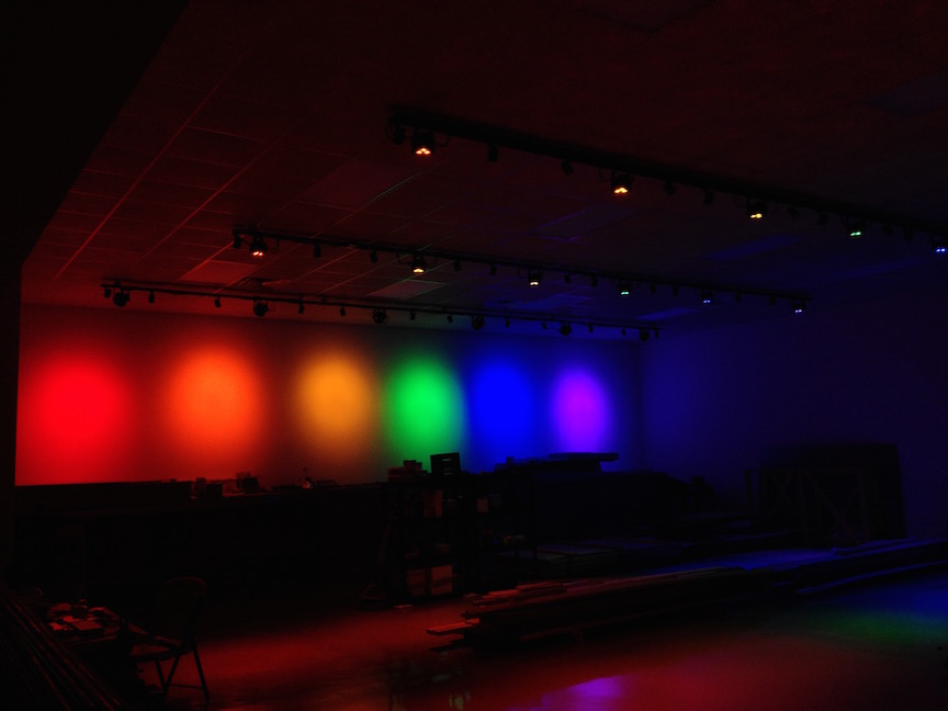
One challenge, however – high ceilings come with added work in lighting design. Special-effects lighting was part of the overall plan, including daylight, sunset/sunrise and night ambience, and possibly a stormy pall over the layout. Key objective here was all lighting was to be LED. Effective large-space LED lighting was prohibitively expensive during the early phases of construction, but prices fortunately dropped quickly enough to use LED troffers in the drop ceiling for general room lighting.
Research into special effects lighting started with the then-new technology of wireless-controlled color-changing light bulbs marketed to early-adopter consumers. The reality was disappointing: the bulbs were expensive, not very bright, and they had a limited palette of colors. Especially a problem was the number of bulbs controllable by the hub, constrained to maybe a quarter of what was needed for the full system, and multiple hubs in the same space were not supported due to network protocol limitations.
So scratch that idea. Even though there are now many more choices, improved color control and lower costs than when we started, and the limitations and complexities are different, there are still weaknesses that make the consumer-grade programmable color-changing lighting unsuitable for the layout project.
LED stage lighting was becoming affordable in the interim, with spotlights and effects lighting tailored for the DJ market. These lower-end stage lights were tested and confirmed as the solution. A support system of steel struts was engineered and added to the ceiling structure, with a wired control network using the DMX512 professional lighting protocol. Track lighting with 5000K white spotlights was added for better “daylight” illumination. Newer, better-performing stage lights (“PAR cans”) are being phased in as time and budget permit. Four banks of stage lights are computer-controlled, with each light separately addressable and available for lighting effects such as sunset and sunrise, moonlit night... and sometimes the occasional thunderstorm.
The Sky
Discussions with fellow modelers about “the best way” to create backdrops yielded three different options: photographed panoramas printed on a large-format inkjet printer, fully-painted backdrops including background scenes such as forests or hills, or the simplest, blue paint.
Photographed panoramas were seriously considered, both commercially-sourced and produced from our own photography such as the image to the right of Kelso, California. Cost of either option was well into four figures given the 140 feet of backdrop. Large-format inkjet printing is expensive, plus we would lose revision flexibility if a layout scene was changed and no longer made sense against the backdrop.
Hand-painted landscape murals were briefly considered, dismissed as too much time and effort. We devised a scheme to paint backdrops on panels which would then allow off-wall production, but the process of hiding the joints and blending the panels added to the work of painting 560 square feet worth of mural.
So... blue paint, maybe add horizon scenes later. Simple. However, the sky was supposed to look somewhat real, and even a well-matched shade would look wrong if monochromatic. A process of fading the blue to a lighter horizon was devised, also gradually changing the blend to the lighter, hazier skies of the Midwest as the layout representation moves from west to east. Horizon scenes are to be addressed with 3D scenery and photographic flats.
The panoramic view of the room to the right also shows the full extent of the sky, the lighting system and also gives a sense of the space.
The Stars
What is a sky without stars at night? As mentioned, much consideration was given to the possibility of special effects for nighttime operations. After a fair amount of research and still under development, a scheme using special ultraviolet-sensitive “invisible” paint from the theater staging industry was devised, coupled with recent improvements in affordable UV LEDs. At left is an early test example of a starry night sky, the UV source we're working with currently has much less visible purple.
Computer Control
Another special feature of the GC&W is layout control performed entirely through computer interfaces. There are no toggle switches or pushbuttons anywhere on the layout controlling power distribution, throwing track switches, or otherwise handling tasks traditionally assigned to manual controls. Under a JMRI supervisor system, touchscreen pads at local control points handle operator controls and display track conditions including turnout positions, block occupancy and signal aspects. Shown here to the right is the panel controlling the junction at "O'Fallons". Communications between the supervisor computer, touch panels and operator throttles are handled through an enterprise-class high capacity WiFi system.
The dispatcher has the option of controlling every operating detail of the layout on his or her dedicated computer, either in a broad view or displaying local panels as needed.
A Virtual Window for Local Railfanning
The original room concept proposed a second level with an observation platform overlooking the layout, with the added bonus of windows to watch passing Canadian National, BNSF, and Norfolk Southern trains 150 feet to the west of the building. As the layout plan developed, access to the observation deck was determined to have too high a cost in layout space. Also, adding the windows was going to be expensive, and would have only afforded views from the deck, anyway. Instead, a dedicated "railcam" system was designed, using a high-resolution professional video camera and a large LCD panel television that could be seen from every point in the layout room.
Return to Home Page